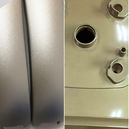
Cutting parameters are the comprehensive set of factors that define the dynamic world of machining. These factors encapsulate the fundamental trio of cutting speed, velocidad de alimentacióny depth of cut. Their orchestration has a profound influence on the performance of any machining operation.
In these parameters, two distinctive categories emerge, each serving distinct purposes. The first is the pursuit of an economic tool life, one that aims to minimize the costs associated with single-part production. This strategy meticulously selects cutting parameters for cost efficiency. The second category focuses on achieving maximum productivity. This is crucial during times of high production demands. Here, the focus is on achieving cutting parameters that optimize productivity even when time is of the essence.
In this article, we will dissect the intricate relationships between cutting speed, feed rate, and depth of cut. Through this exploration, we aim to unveil the secrets behind crafting the perfect cutting formula for any machining task.
Principles of Cutting Parameter Selection
In machining operations, cutting parameters like cutting speed, feed rate, and depth of cut are crucial for the process. The choices made regarding these parameters are not merely technical decisions but strategic ones that impact both productivity and cost-effectiveness. In this section, we will explore the principles behind selecting the ideal cutting parameters and how they can be tailored for different machining processes.
Striking the Balance Between Rough Machining and Precision
When approaching rough machining, the primary objective is to boost production rates. However, this must be balanced with considerations of economic efficiency and processing costs. In semi-finish y mecanizado de acabado, the priority is to maintain top-notch machining quality. At the same time, there’s a focus on optimizing efficiency, cost-effectiveness, and overall production costs. The specific numerical values for these parameters should be determined through a combination of the machine’s specifications, cutting parameter manuals, and practical experience.
The Hierarchy of Parameter Selection for Enhanced Tool Durability
Cuando se trata de choosing cutting parameters, one guiding principle is to prioritize based on tool durability. This involves establishing a hierarchy: first, decide on the depth of cut. Next, set the feed rate. Finally, determine the cutting speed.
During rough machining, the main goal is to boost production rates. However, it’s also important to think about cost-effectiveness and overall economic efficiency. In semi-finish and finish machining, the central concern is to maintain impeccable machining quality while optimizing cutting efficiency and cost-effectiveness. Determine the precise values for these parameters using the machine’s specs, cutting guides, and real-world experience.
In the context of tool durability, the sequence for selecting cutting parameters follows a specific order. The priority is to first establish the depth of cut, followed by determining the feed rate. Finally, setting the cutting speed. This hierarchy ensures that the tool’s endurance is maximized and that the machining process is as efficient as possible.
This process fine-tunes the key aspects of machining. It ensures cutting speed, feed rate, and depth of cut are optimized for the best performance. It is this delicate balance that forms the foundation of effective machining.
Determining the Optimal Depth of Cut
In machining, the depth of cut is a crucial parameter influenced by the rigidity of the machine, workpiece, and herramientas de corte. Its selection plays a vital role in achieving efficient and productive operations. This section will delve into the principles of determining the ideal depth of cut, considering various surface roughness requirements and the impact of rigidity.
Leveraging Rigidity for Efficient Machining
The depth of cut is contingent on the rigidity of the machine, workpiece, and tool. Under conditions where rigidity permits, it is advisable to set the depth of cut to match the machining allowance on the workpiece. This approach not only minimizes the number of tool passes but also significantly enhances production efficiency.
The guiding principles for determining the depth of cut are as follows:
Principle 1: In cases where the workpiece’s surface roughness requirement falls within the range of Ra12.5μm to 25μm, and the machining allowance for CNC machining is less than 5mm to 6mm, a single rough machining pass is adequate to meet the requirement. However, when dealing with larger allowances, subpar process system rigidity, or insufficient machine tool power, dividing the operation into multiple passes becomes the preferred approach.
Principle 2: For workpieces with a surface roughness requirement of Ra3.2μm to 12.5μm, it is feasible to split the operation into two steps: rough machining and semi-finish machining. In rough machining, the depth of cut should be selected as in the previous principle. After rough machining, a margin of 0.5mm to 1.0mm is left, which is subsequently removed during the semi-finish machining phase.
Principle 3: For workpieces with a surface roughness requirement of Ra0.8μm to 3.2μm, a three-step process is recommended, involving rough machining, semi-finish machining, and finish machining. During the semi-finish machining phase, a depth of cut of 1.5mm to 2mm is considered optimal, while in the finish machining stage, a depth of cut of 0.3mm to 0.5mm is preferable.
Determining the Optimal Feed Rate
The feed rate is a vital cutting parameter closely tied to the precision of the workpiece, surface roughness requirements, and the materials of the tool and workpiece. The maximum feed rate depends on both the machine’s rigidity y el feed system’s performance.
Precision and Surface Quality in Feed Rate Selection
Determining the right feed rate is a critical aspect of machining. It depends on precision, surface roughness, and materials for the tool and workpiece. Moreover, the selection is significantly affected by the capabilities of the machine tool, particularly its rigidity and the overall performance of the feed system.
The principles for establishing the optimal feed rate are as follows:
Principle 1: When the quality requirements for a workpiece can be assured, opting for a higher feed rate becomes a viable strategy to enhance production efficiency. Typically, feed rates ranging from 100 to 200 meters per minute are considered optimal within this context.
Principle 2: In situations where tasks involve cutting-off operations, deep-hole drilling, or the use of high-speed steel tools, a preference for lower feed rates is advisable. Here, feed rates in the range of 20 to 50 meters per minute are typically employed, ensuring that the quality of the machining process remains uncompromised.
Principle 3: In tasks that require strict precision and high surface quality, it’s best to use a lower feed rate. For these situations, opting for feed rates between 20 to 50 meters per minute is advisable to attain the desired precision and surface quality.
Principle 4: During non-cutting movements, use the machine tool’s maximum feed rate from the CNC system for efficiency. This is especially helpful during long returns to the initial position This practice is especially useful when optimizing non-cutting travel, resulting in efficient and time-saving operations.
Determining the Optimal Spindle Speed
The spindle speed is a pivotal component of the cutting parameters in machining. To make the right choice, you need to consider the allowable cutting speed and the size of the workpiece or tool with precision.
Selecting the right spindle speed is a critical aspect of machining. It is a parameter that is intrinsically linked to the allowable cutting speed and the diameter of the workpiece or tool. The calculation of this parameter follows a specific formula:
n = 1000 * v / π * D
Where:
- v represents the cutting speed, measured in meters per minute and determined by the tool’s durability.
- n denotes the spindle speed, measured in revolutions per minute (r/min).
- D signifies the diameter of the workpiece or tool, measured in millimeters (mm).
The calculated spindle speed, represented by n, should ultimately align with the specifications found in the machine tool’s instruction manual or select a value that closely approximates it.
Cutting Parameters in Action: Calculating Depth of Cut, Feed Rate, and Cutting Speed
In machining, it is essential to understand how the interplay of various parameters affects the machining process. These calculations are pivotal in achieving precision and efficiency in machining processes.
Calculating Depth of Cut (ap)
Depth of cut, also known as “ap,” is a fundamental aspect of machining, representing the vertical distance between the machined surface and the surface awaiting machining. It is the measure of how deeply the tool cuts into the workpiece during each feed. In order to calculate the depth of the cut, the following formula is applied:
ap = (dw – dm) / 2
Where:
- ap signifies the depth of cut in millimeters (mm).
- dw is the diameter of the workpiece’s surface awaiting machining in millimeters (mm).
- dm is the diameter of the workpiece’s already machined surface in millimeters (mm).
For example, if the diameter of the surface awaiting machining is Φ95mm, and a single feed carves it down to Φ90mm, the depth of cut can be calculated as:
ap = (dw – dm) / 2 ap = (95 – 90) / 2 = 2.5mm
Determining the Feed Rate (f)
The feed rate, represented as “f,” shows how the cutting tool moves concerning the workpiece or, in simpler terms, it’s the tool’s motion during one complete revolution. This parameter varies depending on the feed direction. It can be either longitudinal, along the lathe bed guide rails, or transverse, perpendicular to the lathe bed guide rails.
You can calculate the feed rate using this formula:
vf = f * n
Where:
- vf is the feed rate in millimeters per second (mm/s).
- n represents the spindle speed in revolutions per second (r/s).
- f is the feed rate in millimeters per second (mm/s).
Calculating Cutting Speed (vc)
Cutting speed, represented as “vc,” is the speed of the cutting edge at a given moment in relation to the primary movement of the workpiece. To calculate the cutting speed, the following formula is employed:
vc = (π * dw * n) / 1000
Where:
- vc represents the cutting speed in meters per minute (m/min).
- dw is the diameter of the workpiece’s surface awaiting machining in millimeters (mm).
- n is the workpiece’s speed in revolutions per minute (r/min).
When making calculations, it’s essential to use the maximum cutting speed, which occurs at the surface diameter during girando. This is critical because this is where the speed is highest and tool wear is most significant.
In practical machining scenarios, the diameter of the workpiece is usually known. With this information, factors like workpiece material, tool materialy machining requirements are considered to determine the cutting speed. This speed is then converted into the lathe’s spindle speed, which is critical for machine tool adjustment. The formula for this conversion is:
n = (1000 * vc) / (π * dw)
For instance, when turning the outer diameter of a Φ260mm pulley on a CA6140 horizontal lathe and selecting a cutting speed (vc) of 90m/min, the spindle speed (n) can be determined as:
n = (1000 * vc) / (π * dw) n = (1000 * 90) / (3.14 * 260) = 110 r/min
Following the calculation of the spindle speed, it is advisable to choose a value close to it from the machine’s specifications, typically rounded to 100 r/min, as the actual spindle speed for the lathe.
Partnering with Prototool for Precision CNC Machining
Cutting parameters encompass cutting speed (vc), feed rate (f or vf), and depth of cut (ap). These factors are the lifeblood of CNC machining, guiding the intricate dance of tools and materials to shape and refine the workpiece.
En Prototool, we have mastered the art of CNC machining, leveraging our expertise in cutting parameters and their harmonious relationships to deliver top-tier results. Our commitment to excellence and precision has made us a trusted partner for businesses seeking high-quality Servicios de mecanizado CNC.
We comprehend that the choice of cutting parameters is more than just a mathematical calculation; it’s an art, a science, and a craft. It requires a delicate balance between optimizing production rates while considering the cost-effectiveness and quality of the final product. Our team of skilled machinists and engineers excels in this art, and we stand ready to offer our expertise to elevate your CNC machining projects.
As a CNC machining service provider, Prototool excels in assisting you in finding the perfect equilibrium in cutting parameters. Whether you require an aggressive approach to boost productivity or a meticulous one to attain the finest surface finish, we tailor our services to match your specific needs. Our depth of knowledge in cutting parameters ensures that your projects are executed with utmost precision and efficiency.


