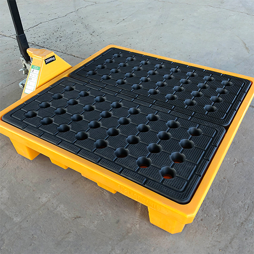
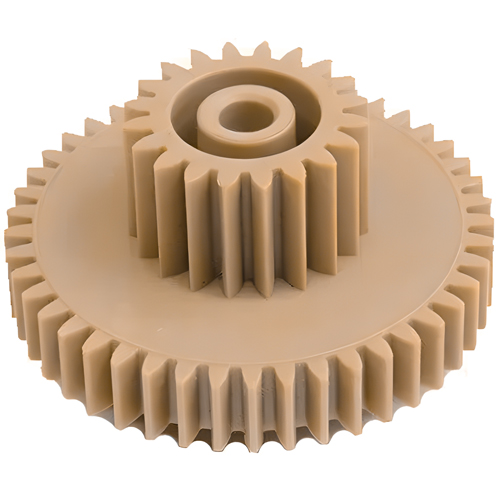
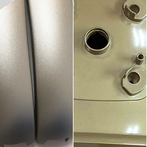
Injection molding is a cornerstone in plastic parts’ fabrication, playing a pivotal role in diverse industries. From medical equipment to automotive interiors, electronic housings to everyday housewares, and beyond, the ubiquity of injection molded parts is undeniable.
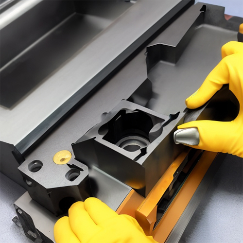
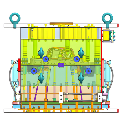
The process involves melting raw plastic in an injection molding machine, shaping it within a mold, and allowing it to cool and solidify, producing intricately designed components.
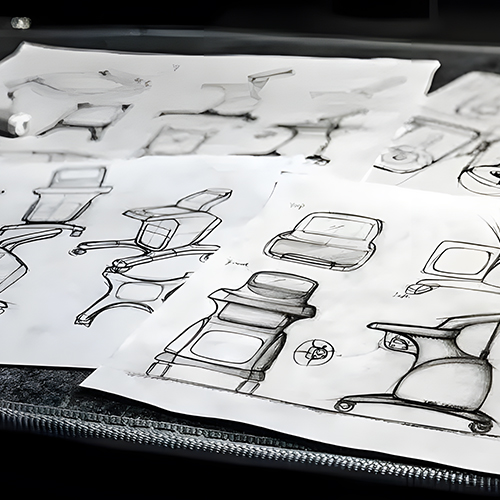
The complexity of plastic parts design demands meticulous attention to various factors, including functional requirements, material selection, and structural considerations. Among the key elements crucial to this design process are wall thickness, draft, textures, ribs, and, notably, bosses.
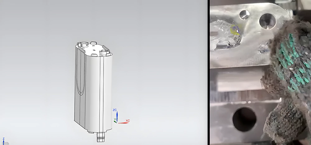
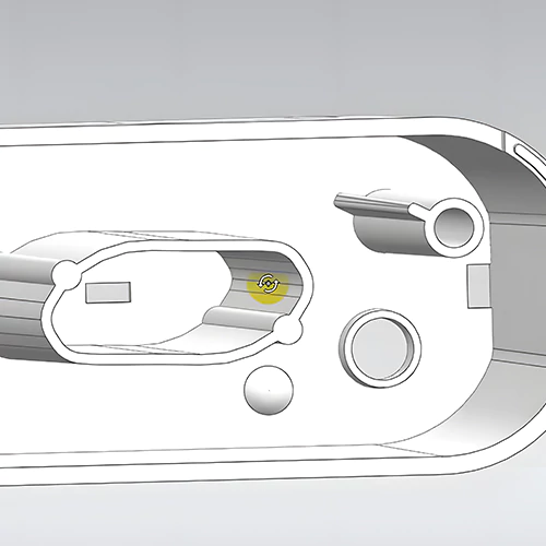
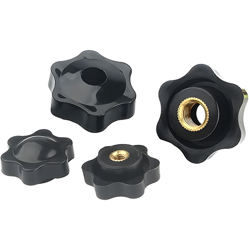
Serving as points of attachment and assembly, bosses are commonly cylindrical projections with strategically placed holes for screws or threaded inserts. Ensuring their effective design is paramount, requiring generous base radii for strength and ample draft for seamless part removal from the mold.
This blog delves into the fundamental guidelines for boss design in injection molded parts, aiming to enhance moldability, extend mold life, increase part operational longevity, and reduce manufacturing costs.
Boss Design: A Brief Overview
In plastic molded part design, a crucial element demanding attention is the concept of boss design. What precisely constitutes a boss within molded parts? At its core, a boss is a structural feature—a cylindrical projection featuring strategically placed holes within molded components.
The primary function of bosses encompasses providing attachment points for screws, fasteners, or other essential assembly hardware. These features play a pivotal role in facilitating smooth assembly processes while ensuring the final product’s structural integrity.
Understanding and mastering boss design is indispensable for optimizing the functionality and manufacturability of plastic molded parts.
Boss Design Elements
Effective boss design is pivotal for the structural integrity of molded parts. To achieve optimal strength without compromising the overall design, several key elements demand careful consideration:
Thickness Ratio
The wall thickness of bosses should not exceed 60 percent of the main wall thickness of the part. Striking this balance is crucial to ensure the boss’s strength without compromising the molded part’s overall structural integrity.
Base Radius Ratio
Stability and warp prevention during manufacturing rely heavily on the base radius ratio. A base radius should be at least 25 percent of the main wall thickness, providing a robust foundation. This corresponds to a base diameter of at least 50 percent, contributing to the overall resilience of the boss.
Connection to Adjacent Walls
Bosses should always be connected to adjacent walls using ribs or gussets. This strategic connection helps avoid the creation of thick sections, minimizing the risk of warping during the manufacturing process. Thoughtful design ensures a seamless integration of bosses into the overall part structure.
Fillet Ratio at the Base
As a point of attachment between two surfaces, the base of bosses requires a fillet ratio for added strength. This preventive measure safeguards against potential stresses induced by the insertion of screws or other hardware, ensuring resilience and minimizing the risk of fracture.
Incorporating a fillet ratio is a critical step in enhancing the longevity and reliability of the boss within the molded part.
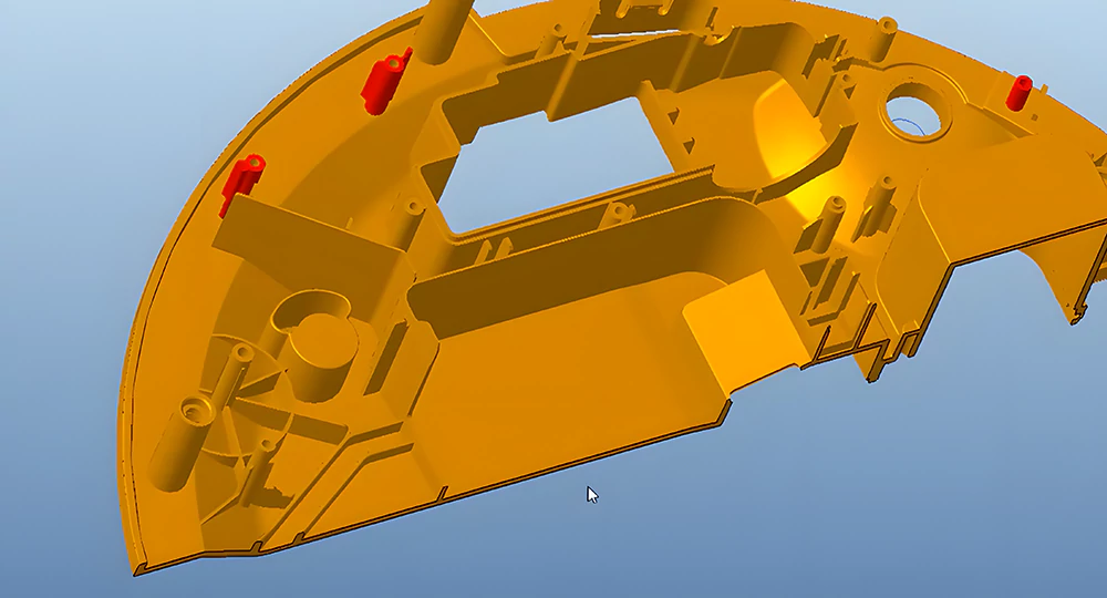
10 Critical Boss Design Guidelines for Molded Plastic Parts
1. Minimum Radius at Base of Boss
Implementing a fillet with a specific minimum radius at the base of a boss is imperative to mitigate stress concentration. This radius is strategically placed where the boss intersects with the nominal wall, effectively reducing stress and enhancing overall structural integrity.
While the radius provides strength, it should be carefully controlled to avoid thick sections, balancing structural support and manufacturability. The recommended range for this base radius is 0.25-0.5 times the nominal wall thickness, ensuring optimal performance during the molding process.
2. Spacing between Bosses
The strategic placement of bosses is crucial for preventing the creation of thin areas that pose challenges in the cooling process. Maintaining a suitable spacing between bosses, ideally at least 2 times the nominal wall thickness, is essential for efficient cooling and quality improvement.
Proximity between bosses can lead to difficulties in cooling, affecting productivity and mold life. Proper spacing is key to ensuring uniform cooling and enhancing the longevity of the mold.
3. Radius at Base of Hole in Boss
Introducing a radius at the base of the hole in a boss serves multiple purposes, including avoiding sharp corners and stress concentration. This design feature aids in the molding process and contributes to stress reduction, ensuring the longevity of the molded part.
The recommended radius at the base of the hole in the boss falls within the range of 0.25 to 0.5 times the nominal wall thickness, striking a balance between manufacturability and stress reduction.
4. Minimum Draft for Boss OD
Ensuring an easy ejection from the mold requires a suitable draft on a boss’s outer diameter (OD). This draft, typically greater than or equal to 0.5 degrees, facilitates a smooth demolding process.
An adequate draft on the boss’s outer surface not only streamlines manufacturing but also contributes to the efficiency of the injection molding process, minimizing production challenges.
5. Minimum Draft for Boss ID
Design considerations often necessitate a minimum taper on a boss’s inner diameter (ID) for proper engagement with fasteners.
A draft greater than or equal to 0.25 degrees on the inner walls of the boss is recommended, ensuring seamless demolding and establishing a secure fit for fasteners. This draft on the ID contributes to both the manufacturability and functionality of the final molded part.
6. Boss Height to OD Ratio
Striking the right balance in the boss’s height relative to the outer diameter (OD) is crucial for preventing undesirable material mass and thick sections at the base.
With a recommended height of less than three times the outer diameter, this design guideline supports effective cooling, reduced cycle time, and dimensional accuracy for cored holes. A proper height-to-OD ratio is essential for optimal part performance.
7. Minimum Radius at Tip of Boss
To endure varying loadings during service conditions, providing a fillet with a specific minimum radius at the tip of a boss is essential. This design feature effectively reduces stress concentration and enhances the overall durability and life of the molded part.
The recommended minimum radius at the tip contributes to the overall resilience of the boss under different loading scenarios.
8. Chamfer at the Top of Boss
Incorporating a chamfer at the top of a boss is a beneficial lead-in for fasteners during the assembly process. This design feature ensures smooth engagement and alignment during assembly, streamlining the manufacturing process.
The chamfer at the top of the boss contributes to the ease of assembly and the overall quality of the final molded part.
9. Wall Thickness of Boss
Maintaining an ideal wall thickness for bosses, approximately 60 percent of the nominal wall, is critical to prevent issues such as voids, sink marks, and extended cycle times.
While exceeding this thickness can lead to manufacturing challenges, adjusting the wall thickness may be considered for bosses in non-visible areas, allowing for increased stresses imposed by self-tapping screws. Striking the right balance in wall thickness is essential for optimal part performance.
10. Standalone Boss
Implementing coring for bosses and other thick sections is recommended to ensure uniform material flow and load distribution. Attaching the boss to the sidewall enhances rigidity and material flow, contributing to the overall structural integrity of the molded part.
This design consideration is crucial for achieving improved part performance and manufacturability.
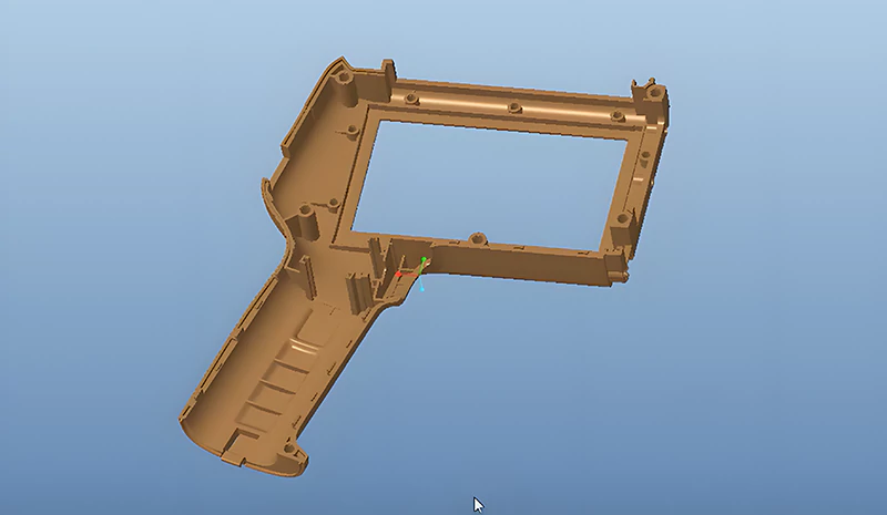
The Challenges and Solutions in Boss Design
Improper boss design poses challenges that can significantly impact the aesthetics and functionality of molded parts. What are these challenges? How can you solve them? Let’s explore below.
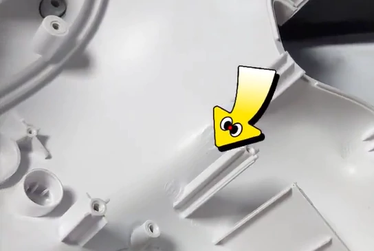
Causing Sink Marks and Warpage
Challenge
One of the primary challenges in boss design is the potential for sink marks and warpages. When bosses are inadequately designed—either excessively thick or lacking proper reinforcement—they cool at different rates than the surrounding areas.
This temperature disparity can lead to unsightly sink marks, creating depressions on the surface and warpage, causing the part to deviate from its intended shape.
Solution
Addressing this challenge involves optimizing the wall thickness of bosses and incorporating reinforcement ribs. Proper wall thickness ensures uniform cooling, minimizing the risk of sink marks and warpage. Reinforcement ribs are crucial in distributing stress evenly across the boss, preventing localized deformation and enhancing overall part integrity.
Impact on Cooling Time and Cycle Time
Challenge
Bosses directly influence cooling and cycle times during the molding process. In cases where bosses are excessively thick or poorly designed, they may trap heat, resulting in prolonged cooling and cycle times.
This not only slows down the manufacturing process but also leads to increased production costs.
Solution
Mitigating the impact on cooling and cycle times involves strategic adjustments to the cooling channels within the mold. Optimizing the overall mold design, with particular attention to the placement of bosses, can minimize the adverse effects on cooling and cycle times.
Limited Material Selection and Compatibility
Challenge
The material selected for molded parts significantly influences boss design. Choosing an incompatible material can subject the boss to excessive stress, potentially leading to cracking or failure.
Solution
Overcoming this challenge revolves around selecting the right material for boss design. Opt for a material with the necessary strength, stiffness, and chemical resistance to ensure the boss can withstand the loads and environmental conditions.
Material selection is crucial for achieving durable and reliable boss designs in molded parts.
Conclusion
Bosses in injection molded parts serve as crucial features, acting as anchors, supports, and facilitators of reliable assembly. These components play a crucial role in ensuring the final product’s structural integrity and optimal performance.
Adhering to fundamental design guidelines is imperative to produce plastic parts with robust, functional, and visually appealing bosses.
For those seeking top-quality molded parts with a dependable boss design, Prototool emerges as the optimal choice. Our injection molding services are backed by an experienced team committed to meeting your specific requirements. Want to know more? Get in touch today!

